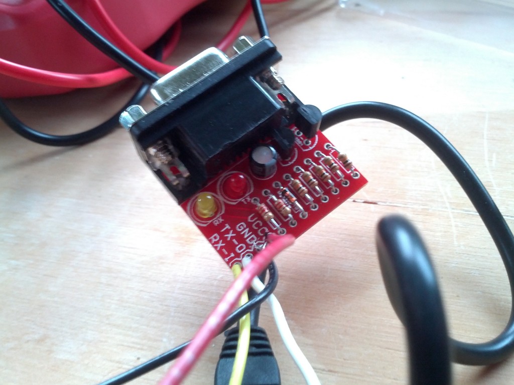
As part of my project to make an Arduino based watchdog for my home server, I went and picked up a proper soldering iron today and assembled the RS232 Shifter Circuit I had purchased from Sparkfun/Mindkits.
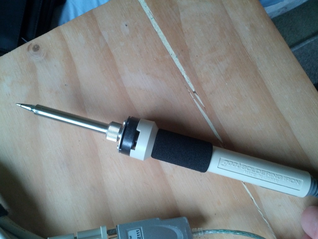
I ended up getting a Goot soldering iron – it wasn’t too cheap, but the reviews I was reading online suggested it was the next best thing to a proper soldering station and a quality Japanese tool. It’s also 46W, so much better for the lead-free solder I’m using, compared to the crappy 15W DSE brand generic iron I was using previously.
It made a massive difference to the soldering efforts, the lead-free solder melted without issue and flowed smoothly – plus the fine point conical tip made getting the solder into key areas a lot easier.
The tips are changeable and I’ve been advised by an electronics fixing friend to get a set of tip types, as certain ones suit different tasks better than others.
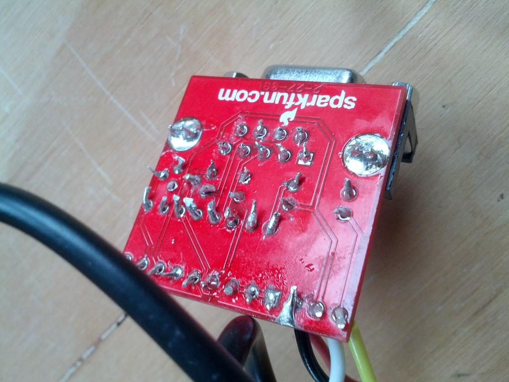
Whilst the new soldering iron is a huge improvement, my soldering skill is still a bit poor, I had a few text-book joins where the solder flowed perfectly and bonded with a smooth shiny surface, but a lot of my joins tend to be slightly one sided, where the solder hasn’t flowed right around the components lead and PCB hole which makes then a bit weak.
I’m also tending to leave too much solder on the component lead, which leaves larger joins than really needed, so need to work on how much solder I apply.
After constructing the circuit, I gave it a test by connecting the TX and RX of the shifter circuit to the TX and RX on the Arduino, which basically uses the Arduino as an UART to RS232(over USB) adapter.
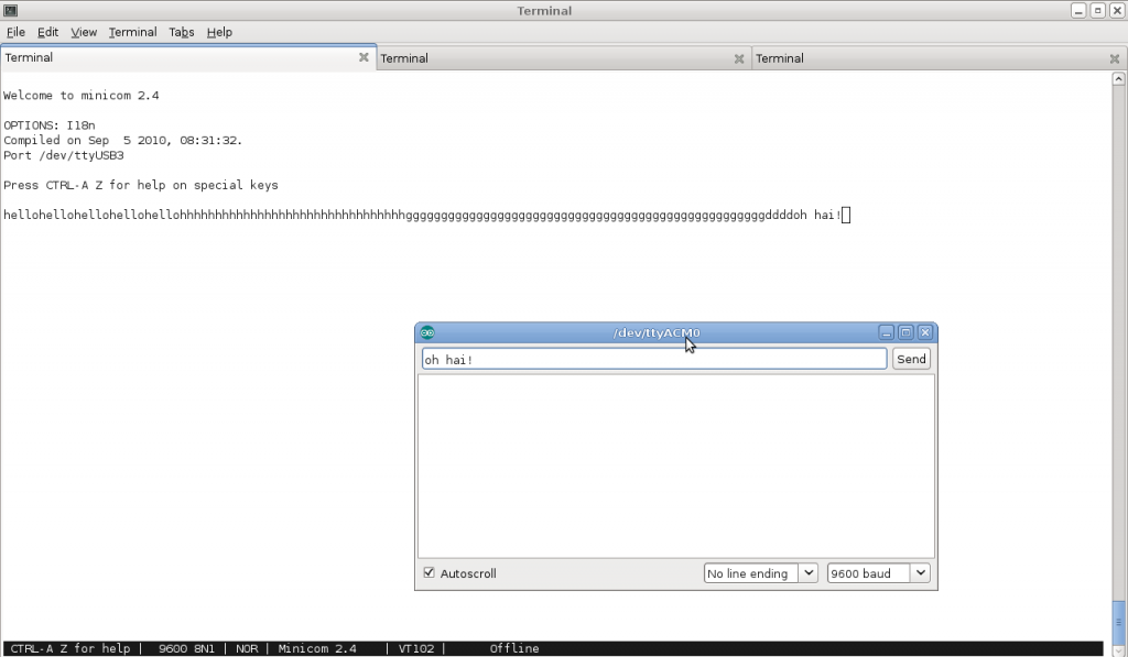
Then I connected the new DB9 port to my laptop and typed messages into the Arduino serial monitor, to have them passed through my new circuit and into my laptop’s DB9 port.
Amazingly, things worked first time and I’m able to successfully receive data via the shifter board – in my quick test TX from the shifter board wasn’t working, but it may have been a serial speed/config issue that I just need to tweak in the OS, rather than the board itself.
The next step is connecting this shifter circuit to the digital I/O ports on the Arduino and using the software serial library to add a second serial port to the device. I can then do the same to the HTC Magic serial break out and I’ll basically have an Arduno with 3 serial ports in total – the onboard UART, the DB9 PC via shifter and the HTC magic.
Once that’s done, it’s just a case of writing the software needed to turn the collection of hacks into a hardware watchdog and serial remote access system. :-)
And once that’s all working, I’ll build a final solution using one of the Arduino prototyping shields from Freetronics, which will include all the shifter circuitry onboard and just provide a 2×5 IEC pin header to plug a ribbon cable directly into the server’s motherboard serial port header.


