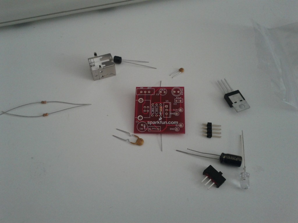
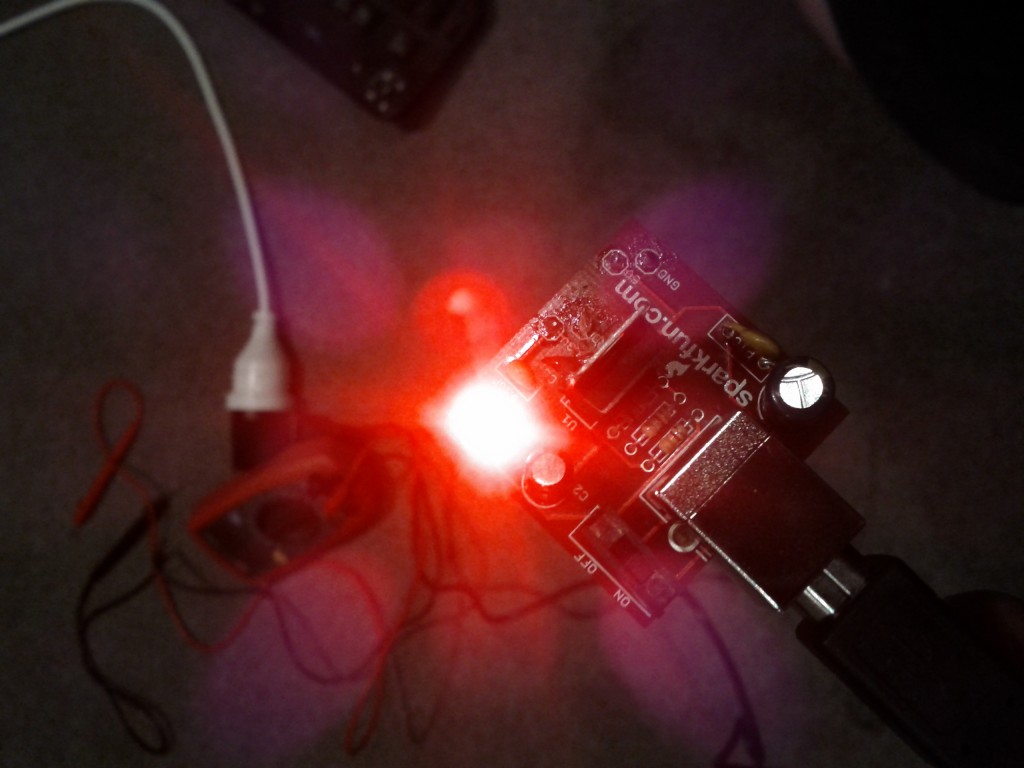
As part of my efforts to learn more about electronics, I recently obtained a power supply kit that breaks the standard 5V USB output into 3.3V and 5V bread-board connectable outputs from Mindkits (who resell Sparkfun kits in NZ, amongst other stuff).
I went for a USB-powered model rather than a typical round-pin DC supply, since I have an abundance of USB power sources with me all the time (both laptop and wall adaptors) and it’s much better than having yet another damn power brick hanging around.
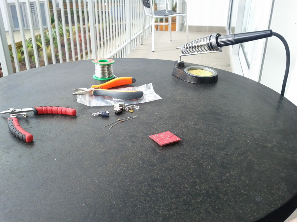
I finally managed to get around to making the time to try it out this weekend and dug out the soldering iron to tackle the challenge – past soldering exploits have never fared particularly well, but I figure sooner or later I’ll learn something and make a working device. ;-)
One of the biggest challenges I found was actually holding such a small PCB still, whilst trying to align solder and the iron – think one of my next purchases will be some sort of clamp to hold the board in place.
I’m not convinced that my soldering iron is particularly good either, need to do some research on the best type of soldering head (round vs chisel?). I’d probably go better with more gun shaped soldering iron than the round pencil design, I just tend to find it easier to align.
I started off doing the small components like resisters and small caps, before moving on to the voltage regular, switch, USB port and pin headers.
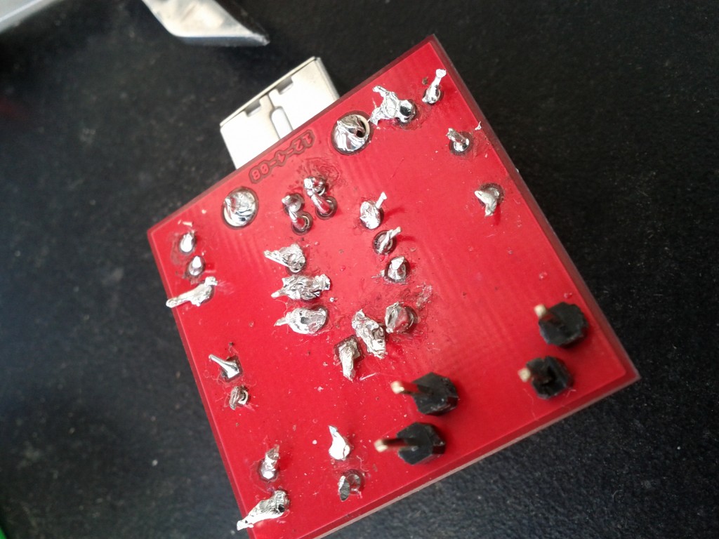
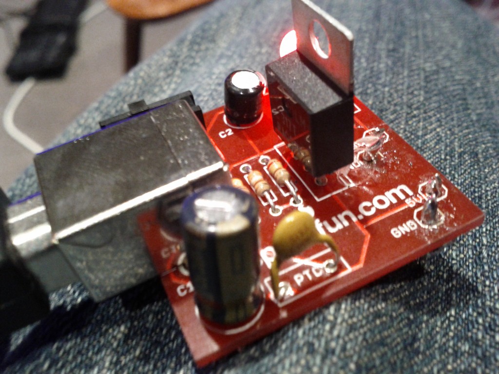
Apologies to any electrical engineers or skilled hobbyist reading this blog, but my soldering is pretty terrible, as you can see. Take note that this is the first thing I’ve soldered that actually works :-P
I started with the resisters in the middle, as you can see my soldering was pretty terrible there – used too much solder and ended up making large messy blobs.
Later I got better at briefly heating the legs and then applying the solder in a way that allowed it to run down and bond with the PCB, so my later joins got a lot better, eg the USB socket with it’s 4 close small pins.
I got an impromptu lesson to using a multimeter as the circuit wouldn’t work initially – I had managed to make a PSU that was always on (ignoring the switch status) and provided no 3.3V output.
Thanks to the simplicity of this kit, it was pretty easy to test each component to figure out where my bad joins were and I re-soldered a few of the bad earlier joins.
The only real headache was the voltage regulator – for some reason I had real difficulty getting the solder to bond with the middle pin and the PCB and had to redo it several times – it’s still not perfect TBH :-(
So far the kit seems pretty good, it was really easy to assemble with the clear silkscreen markings – most work I had to do was lookup the resister code/colors, which is trivial thanks to Electrodroid on my phone. :-)
The one design issue I do have with the kit, is that the positioning of the breadboard connectors requires you to break the header pins into single units, but doing this really weakens the design, since it’s just one tiny solder joint holding the pin to the PCB – I do fear the force of inserting and removing from breadboards will wear it down a bit over time.
To counter this a bit, I’ve stuck a blob of hot glue around the headers, to give them a bit more integrity – although the 3.3V pin soldering joint is playing up and might need redoing anyway.
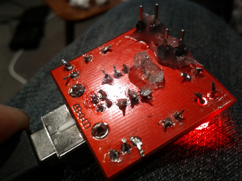
Hot glue solves all! (also stuck some around the voltage regulator as one of the solder joints isn't that great, but I can't fix it without risking ruining the PCB trace)
Looking at the round-DC connector version of the kit, the design instead has two pairs of 2x pin headers, which I suspect will make it a bit more sturdy.
Overall whilst it’s a painful learning curve trying to get the soldering right, I didn’t burn myself *too* badly and whilst not a shining example of art, the board works and powers up.
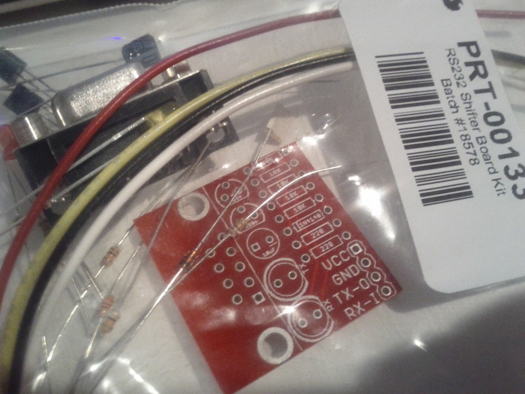
Next time, I’ll be tackling the RS232 shifter kit and then working to hook up an RS232 power to an Arduino’s digital pins using a software serial driver. And after that, I might have a go at making some temperature sensor 1-wire boards to install around my server case using the small square prototyping boards I brought.
Hopefully by then my soldering will be an acceptable level. :-)
